Building the Bridge: How a Model Helped to Transform a Roofscape
In Bentonville, Arkansas, a new approach to medical education is taking root at the Alice L. Walton School of Medicine, an institution founded on the principles of whole health and a deep connection to the natural beauty of the Ozark region. This innovative spirit extends to the very architecture of the campus, where a green roof meets lightweight geofoam and precise GPS technology to create a surface that blurs the lines between building and landscape. Here, the roof doesn’t just top the building—it becomes a living, walkable terrain, flowing seamlessly from the surrounding trail network and embodying the school's commitment to well-being and its unique Ozark setting. This rooftop landscape, envisioned and designed by Polk Stanley Wilcox Architects and OSD (Office of Strategy + Design), is more than just an ambitious design; it’s a testament to a powerful collaboration that redefines the possibilities of construction sequencing and coordination.
The school’s roofscape—designed by OSD—presented a new construction opportunity for Ozark Green Roofs. Green roof design at this complexity and scale represents a relatively new frontier in the US, demanding a unique approach to planning and execution. Inspired by the collaborative vision of Polk Stanley Wilcox Architects and OSD, the intricate grading contours were designed to mirror the rolling forms of the Ozark region, with features like the central runnel, a steam-like channel to direct water, echoing natural water pathways. This ambitious design aimed to capture the distinctive character of the local landscape, particularly its bluff formations, while creating an environment that aligns with the school’s focus on health and connection to nature.
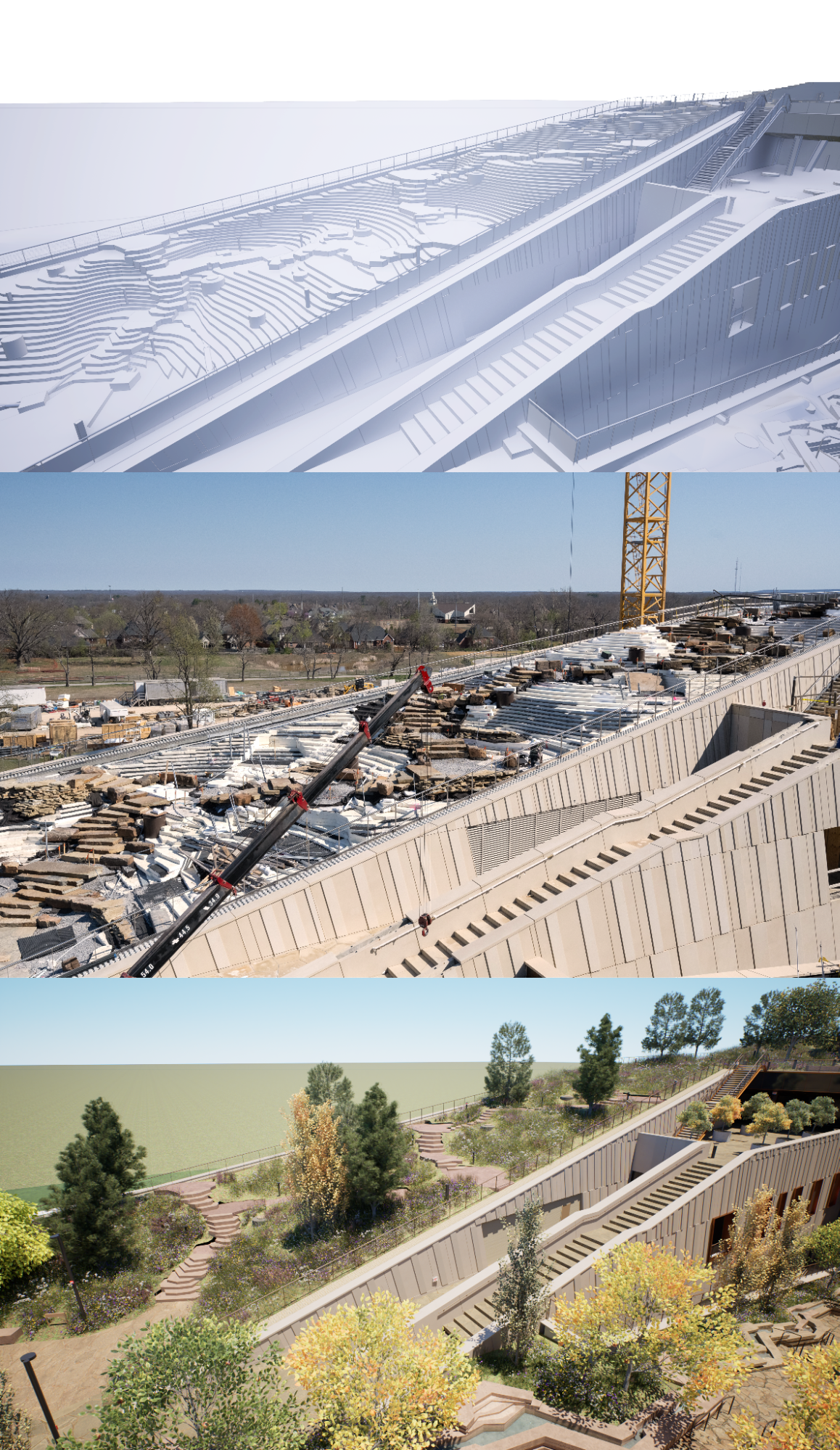
To provide the construction team with a truly tangible understanding of the project, Ozark Green Roofs engaged Catalpa Architects to develop a detailed, construction-ready model of the green roof as it would exist in reality to assist with construction complexities. Building upon a base model from Polk Stanley Wilcox Architects, Catalpa, under the direction of Chloe Hiley, significantly expanded and refined the visualization. This went beyond simply depicting geofoam, an expanded polystyrene foam used in construction for creating lightweight fills and shaping terrain; it integrated landscaping details, showcasing plant placement and even the visual characteristics of the actual materials to be used. The result was not a static rendering, but a dynamic, almost "pre-built" environment—a video game-like experience that brought the invisible to life, revealing roof slopes, drainage layers, geofoam contours, and fire code compliance. As one installer remarked, it was “eye opening.”
“We needed more than a set of plans,” says Lee Porter from Ozark Green Roofs. “We needed a way to see the job before we touched any materials.”
Rendered in Twinmotion, Catalpa’s BIM (Building Information Modeling) model became the roadmap. BIM is a digital process that involves creating and managing information on a construction project across its lifecycle, integrating data from all stakeholders into a single, collaborative model. This model allowed for real-time grading interpretation, revealed potential clash detection issues—identifying conflicts between different building systems—before they hit the field, and even reduced weight and cost by optimizing geofoam curvatures. Using a GPS rover —a satellite-based navigation system used here to provide precise location data—the crew could install it with precision. The model made material estimation more accurate and installation smoother.
Though the modeling was Chloe’s work, the overall approach was developed in collaboration with her husband and Catalpa Architects co-founder, Kenneth Hiley, who emphasized the importance of thinking through the build process virtually before getting to the job site. “The intent was that there was minimal guesswork in the field,” Kenneth says. “We wanted to build confidence into the process.”
Rather than replacing construction documents, the model complemented them—bringing clarity and continuity to a complex build with many moving parts. It became a shared language among design, construction, and installation teams, turning potential ambiguity into certainty.
A New Terrain for Coordination
For Chloe, the project was familiar in its complexity, but novel in its scale. “This wasn’t just about visualizing design intent—it was about making the design constructible,” she explains. Drawing from a background in 3D visualization that spans academic environments and the creation of 3D educational environments like the Gallery 5 app—which recreated the Crystal Bridges Museum's iconic vaulted gallery and empowered students across Arkansas to curate virtual museum exhibits—Chloe has long been comfortable translating two-dimensional vision into three-dimensional clarity.
This green roof, however, required an especially nuanced interpretation of terrain and topography. The roof deck was the starting point for the model. From there, utilizing the 3D modeling program Rhinoceros, horizontal contours were cut through the roof deck surface. To accurately model the geofoam volume for installation, a corresponding topographical surface was offset downward (representing the soil depth), and this too was sliced at six-inch intervals. These intersecting contours defined the outlines of all the geofoam layers, much like reading a topo map, a map that shows the shape and elevation of the land surface using contour lines, in reverse. This approach made it easier to calculate volumes, plan logistics, and—crucially—communicate the plan across the many trades involved.
Standard BIM processes like clash detection proved indispensable. As mentioned earlier, clash detection within BIM identifies potential conflicts between different building systems. Each trade contributed its own scope on the green roof—including elements like stone, concrete, drainage, geofoam, soil, and plants—and the model served as the stitching mechanism that brought all these components together. But Catalpa’s model went beyond standard coordination—it brought the entire team onto the same visual plane. “We wanted anyone on site to be able to understand the installation process at any angle,” Chloe says. “Not just the superintendents, but every person on the crew.”
Where Passion Meets Process
For Lee and the Ozark Green Roofs team, who are often brought in during later phases of design, this project offered a unique opportunity to engage earlier and more directly in shaping the installation strategy. “Usually we’re working from finalized drawings and interpreting them as we go,” Lee says. “But this time, we had the tools to visualize the build before we ever stepped on site. That changed everything.”
The interactive model didn’t just streamline the logistics—it elevated the craftsmanship. It gave the crew a chance to plan more intentionally, optimize materials, and approach the job with a heightened sense of clarity and confidence. Lee shares, “having a model like this gave us a clear plan and a shared vision.”
That collaborative approach helped the team address the nuances of the roof’s complex geoscape. Geofoam contours were adjusted to reduce material weight without compromising form. GPS (Global Positioning System) Rover data, describing each geofoam contour, enabled enhanced accuracy during installation. Each layer was thoughtfully integrated—horizontal slices of geofoam, aggregate, and soil that together formed a living terrain.
Behind every technical decision was a spirit of resourcefulness. “There’s a lot of care that goes into making up for what we may lack in manpower numbers,” Lee says. “That care was matched by everyone involved, and that’s why it worked. Everyone brought their unique strengths to the table.”
Closing the Gap Between Design and Reality
Perhaps the most lasting impact of this collaboration is how it effectively bridged the traditional gap between design and construction, fostering a closer alignment. This newfound integration was pivotal, transforming what could have been a challenging installation into a repeatable process. By enabling every trade to understand not just the "what" of construction—including the critical step of verifying sightlines, which ensures unobstructed views and proper visual relationships within the design, and confirming exit codes, regulations that specify the requirements for emergency exits in buildings, ensuring safe egress—to streamlining geofoam placement and drainage flow—but also the "why" behind it, the model acted as a digital stand-in for the crucial trust and communication often difficult to achieve on large-scale projects.
Even the way information was presented—concise digital documents, simplified views, and dynamic fly-through visualizations that allowed users to virtually navigate the 3D model—was designed to increase usability for anyone on site. “We wanted to make every crew member’s day easier, especially coordination for Lee,” Chloe says with a smile. “The fewer questions in the field, the more smoothly everything runs.”
Modeling What’s Possible
In many ways, the project sets a precedent for what’s possible when small teams are given the space to innovate. While BIM technology is often associated with large firms and major resources, this collaboration proved that it can be equally transformative—and perhaps more nimble—in the hands of tight-knit, skilled teams with a shared investment in the outcome.
The green roof at the Alice Walton School of Medicine isn’t just an installation—it’s a case study in what happens when design tools become shared construction tools, and when collaboration happens across disciplines and companies, not just within them.
“It’s easy to forget how separated the design and build worlds can be,” Lee reflects. “But this project reminded us that with the right tools and team, those gaps can be closed. And when they are, everybody wins.”